Technical Data
|
Opening temperature:
|
45 °C, 55 °C, 61 °C, 72 °C or 80 °C
|
|
Working temperature:
|
(45 °C - 55 °C) Min. 5 °C/Max. 95 °C
(61 °C - 80 °C) Min. 5 °C/Max. 110 °C
|
|
Ambient temperature:
|
Min. 5 °C/Max. 60 °C
|
|
Max. working pressure:
|
1.0 MPa (10 bar)
|
|
Max. differential pressure:
|
50 kPa (0,5 bar)
|
|
Media 1:
|
Water - Glycol mixture max. 50%
|
|
Thread standard:
|
Rp - female thread
|
|
Material, valve body:
|
Cast Iron EN 1561 EN-GJL-200
|
|
Material, external cover:
|
Coated Aluminium
|
|
Material, cover sealing:
|
Fibre
|
|
Material, sealing:
|
EPDM
|
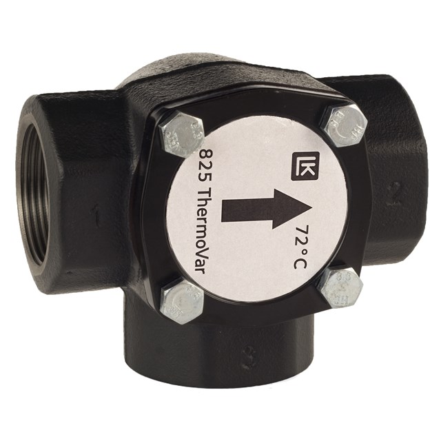
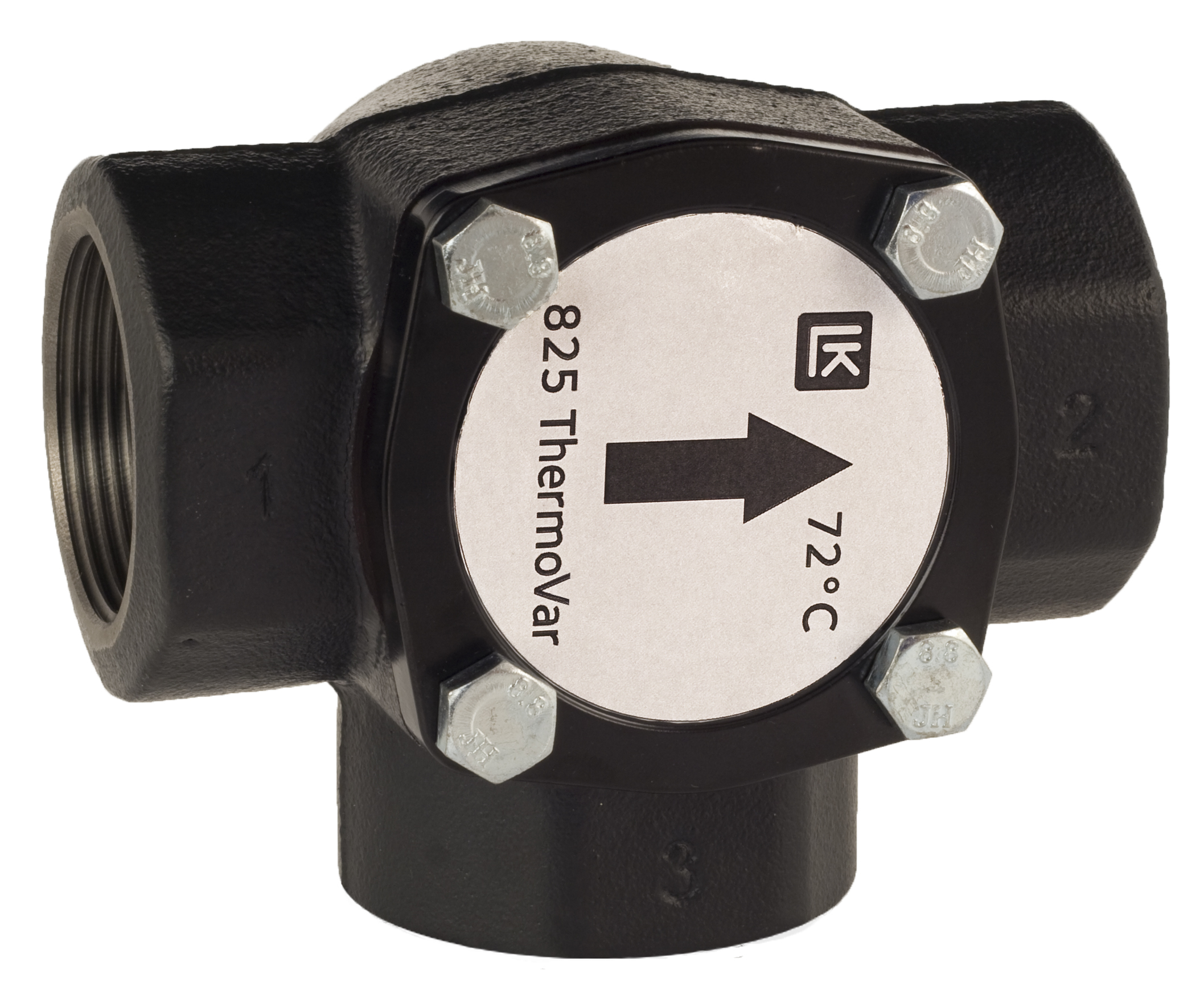
LK 825 ThermoVar® is a 3-way thermic loading valve for solid fuel/storage tank installations. The valve is intended to ensure both an optimal temperature stratification in the storage tank and a high return temperature to the boiler, thus increasing the efficiency of the system. Tarring and condensation are prevented which prolongs boiler life.
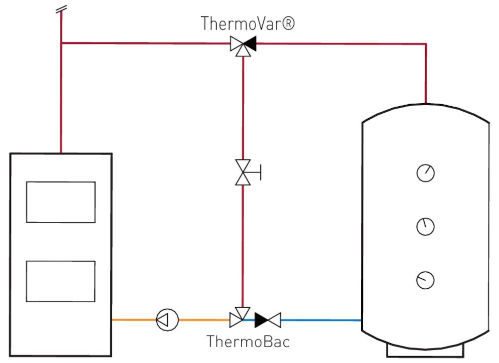
Position I
As soon as the boiler temperature has reached the selected opening temperature, the thermic valve allows hot water to load to the storage tank. Return water from the storage tank is mixed with supply water before it circulates back into the boiler. The loading temperature is at least the selected opening temperature.
A balancing valve should be installed in the circuit between boiler and loading valve.
The installation should be equipped with an LK 822 ThermoBac check valve to prevent self-circulation from storage tank to boiler after the fire has gone out. In case of power failure or pump breakdown the check valve automatically opens for self-circulation.
The circulating pump should be controlled by a thermostat that measures the boiler’s water or flue gas temperature.
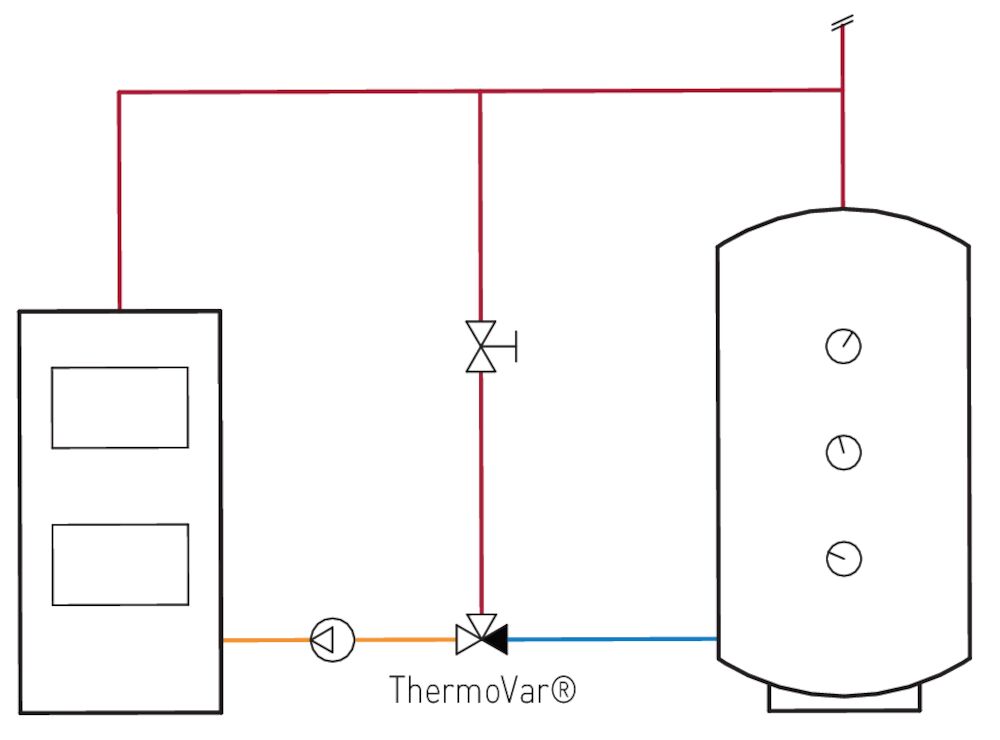
Position II
As soon as the boiler temperature has reached the selected opening temperature, the thermic valve allows return water from the storage tank to mix with supply water before it circulates back into the boiler. The return temperature is at least the selected opening temperature.
A balancing valve should be installed in the circuit between boiler and loading valve.
The circulating pump should be controlled by a thermostat that measures the boiler’s water or flue gas temperature.
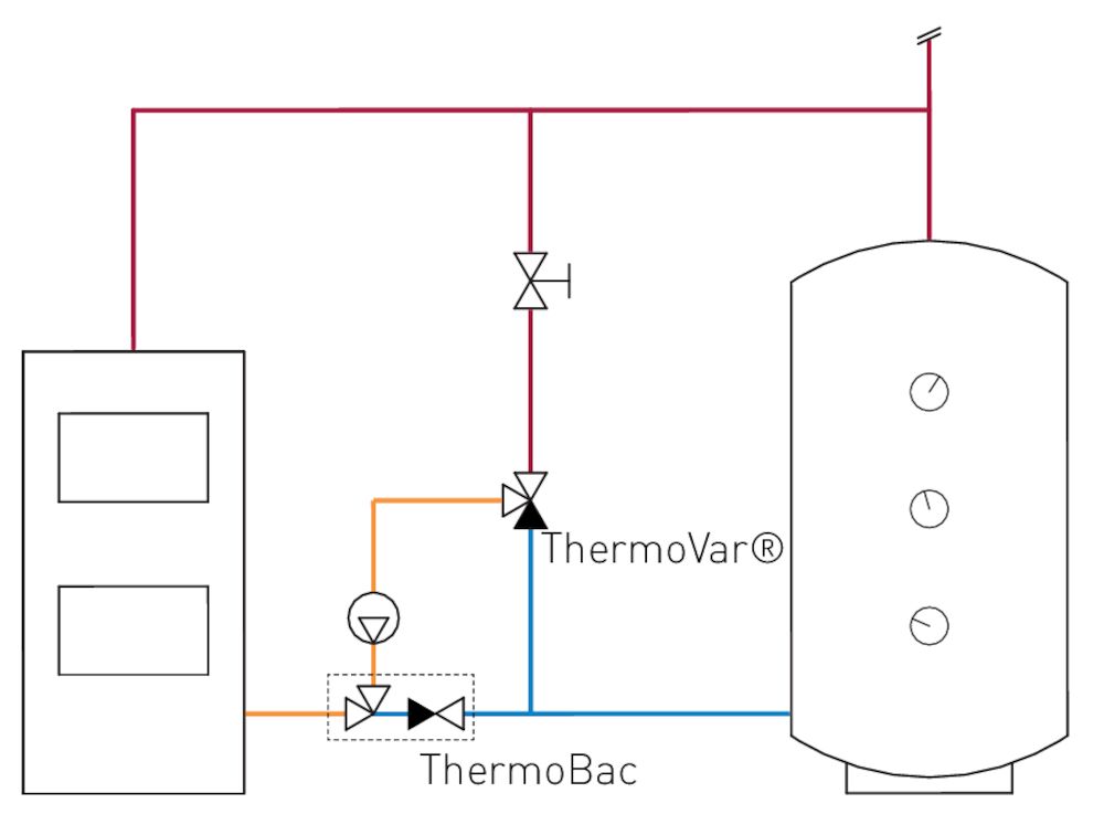
Position III
As soon as the boiler temperature has reached the selected opening temperature, the thermic valve allows return water from the storage tank to mix with supply water before it circulates back into the boiler. The return temperature is at least the selected opening temperature.
A balancing valve should be installed in the circuit between boiler and loading valve.
The installation should be equipped with an LK 822 ThermoBac check valve to prevent self-circulation from storage tank to boiler after the fire has gone out. In case of power failure or pump breakdown the check valve opens automatically for self-circulation.
The circulating pump should be controlled by a thermostat that measures the boiler’s water or flue gas temperature.
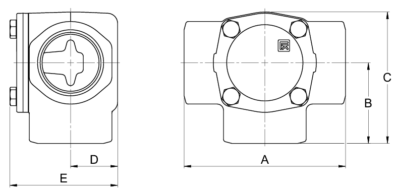
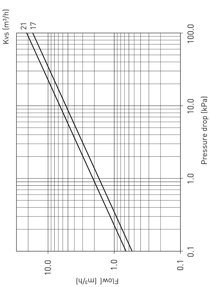
Capacity Diagram
|
Article
|
Opening temp. °C
|
Dim.
|
Kvs m³/h
|
A mm
|
B mm
|
C mm
|
D mm
|
E mm
|
Weight (kg)
|
|
180225
|
55
|
F 1½"
|
17
|
127
|
63.5
|
103
|
37
|
85
|
2.5
|
|
180201
|
45
|
F 1½"
|
17
|
127
|
63.5
|
103
|
37
|
85
|
2.5
|
|
180204
|
45
|
F 2"
|
21
|
127
|
63.5
|
106
|
44
|
101
|
4.0
|
|
180229
|
55
|
F 2"
|
21
|
127
|
63.5
|
106
|
44
|
101
|
4.0
|
|
180249
|
61
|
F 1½"
|
17
|
127
|
63.5
|
103
|
37
|
85
|
2.5
|
|
180254
|
61
|
F 2"
|
21
|
127
|
63.5
|
106
|
44
|
101
|
4.0
|
|
180269
|
72
|
F1½"
|
17
|
127
|
63.5
|
103
|
37
|
85
|
2.5
|
|
180272
|
72
|
F 2"
|
21
|
127
|
63.5
|
106
|
44
|
101
|
4.0
|
|
180285
|
80
|
F 1½"
|
17
|
127
|
63.5
|
103
|
37
|
85
|
2.5
|
|
180288
|
80
|
F 2"
|
21
|
127
|
63.5
|
106
|
44
|
101
|
4.0
|
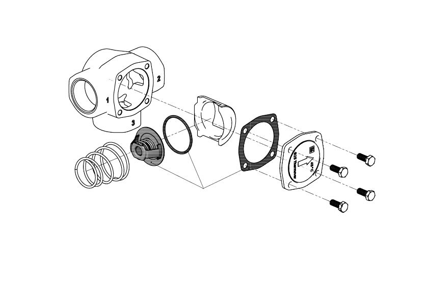
Accessories & Spare parts
|
Article no.
|
Article
|
Position
|
|
180602
|
Thermostatic element 825, 45 °C
|
1
|
|
180603
|
Thermostatic element 825, 55 °C
|
1
|
|
180604
|
Thermostatic element 825, 61 °C
|
1
|
|
180605
|
Thermostatic element 825, 72 °C
|
1
|
|
180606
|
Thermostatic element 825, 80 °C
|
1
|